


From the manual:
" This is a very simple board that has only one function, to allow the display of PC based games on older arcade style monitors. The board needs to be an external device that requires no modification to the software running on the PC. It will handle one of three input resolutions (1024x768, 800x600 or 640x480) with a vertical refresh rate of 60Hz and output to one of two user selectable output modes (640x240@15.72KHz) or (640x384@24.9KHz) The coin-op monitors are RGB noninterlaced and run at 60Hz. The Input of the board will be a DBH-15 VGA analog VGA connector and the output is a 0.156” molex connector with pins for R, G, B, Ground and Syncs.
Input resolutions
· 640x480
· 800x600
· 1024x768
Input Frequency
· Vertical 60Hz
Output resolutions
The uVC board supports multiple output resolutions
Mode 1 - Low Resolution - CGA - (std resolution)
· Horizontal Pixel Clock 73.626 ns
· Horizontal Active Pixels 640 pixels 47.121 μs
· Horizontal Total Pixels 864 pixels 63.613 μs
· Horizontal Front Porch 64 pixels 4.712 μs
· Horizontal Sync Width 60 pixels 4.418 μs
· Horizontal Back Porch 100 pixels 7.363 μs
· Horizontal Scan Rate 15.72 KHz 63.613 μs
· Vertical Line Clock 63.613 μs
· Vertical Active Lines 240 li nes 15.267 ms
· Vertical Total Lines 262 li nes 16.667 ms
· Vertical Front Porch* 3 lines 0.318 ms
· Vertical Sync Width 3 lines 0.191 ms
· Vertical Back Porch 14 lines 0.891 ms
· Vertical Refresh Rate 60 Hz 16.667 ms
Mode 2 - Med Resolution - EGA
· Horizontal Pixel Clock 50.080 ns
· Horizontal Active Pixels 640 pixels 32.051 μs
· Horizontal Total Pixels 800 pixels 40.064 μs
· Horizontal Front Porch 1 6 pixels 0.801μs
· Horizontal Sync Width 80 pixels 4.006 μs
· Horizontal Back Porch 64 pixels 3.205 μs
· Horizontal Scan Rate 24.96 KHz 4 0.064 μs
· Vertical Line Clock 40.064 μs
· Vertical Active Lines 384 li nes 15.385 ms
· Vertical Total Lines 416 li nes 16.667 ms
· Vertical Front Porch* 5 lines 0.200 ms
· Vertical Sync Width 5 lines 0.200 ms
· Vertical Back Porch 22 lines 0.881 ms
· Vertical Refresh Rate 60 Hz 16.667 ms
*Vertical Front Porch Timing is variable based on input frequency "
All example pictures are NANAO MS9 (EGRET II, New Astro City, etc). The best dual-sync monitor (15/24kHz) ever made in my (and many other peoples) opinion.
Note:
I used a 3rd party 360 VGA cable at the time of taking these, but have since upgraded to an official product with noticeable results. There's a slight ghost effect on all pure white objects that's completely gone once I switched to a Microsoft cable.
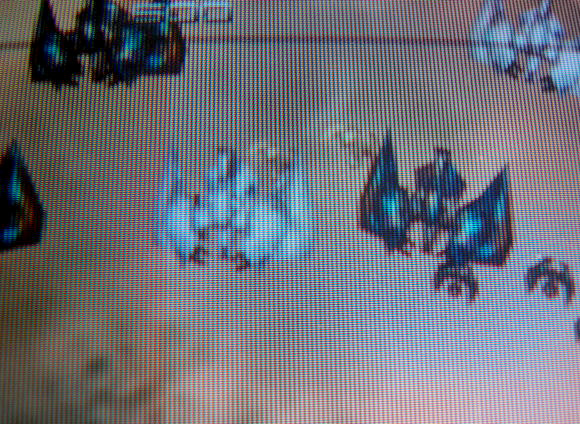
Do-Donpachi Dai-Ou-Jou Black Label Extra (XBox 360) on 15 kHz mode:

Next a couple of pictures not shot by me (but a guy in Japan), with a game not set to vertical on a vertical monitor, hence the monitor scanlines shown incorrectly:
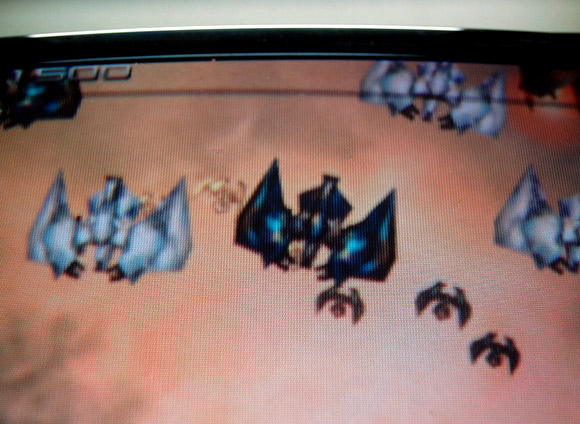
Ikaruga, (XBox 360) on 15 kHz mode:

Ikaruga, (XBox 360) on 24 kHz mode:

Next, some comparison shots between an UVC and an Extron Emotia that I had before finding out about the UVC. The Extron scan converters are superb, but can't except higher input resolutions than 480p and can only output at 15kHz.
The game is Do-Donpachi Dai-Ou-Jou Black Label Extra (XBox 360) on 15 kHz mode:
UVC

Extron Emotia

UVC

Extron Emotia +a lamp reflection, sorry
As you can see in the pictures above, the colors are a bit more vivid from the UVC, but in all fairness, the Extron Emotias aren't made specifically for Arcade monitors, and thus the monitor might need some extra tweaking that I didn't do while taking these photos.
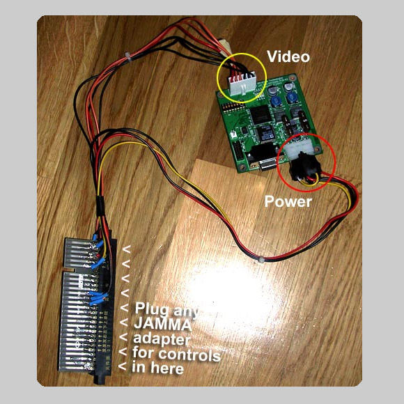
Part list (video only):
1 JAMMA fingerboard
Optional: You can add a female JAMMA connector if you want to use JAMMA adaptors for the PC, console or other high res system's controls like I've done in the picture above
1 ATX HDD/CD power connector
You wire the black wire to GND on the fingerboard, the red wire to +5V and yellow to +12V
1 fitting 6 pin female connector
I got mine from an old PC / ATX "Auxilary power" type connector) for VIDEO (you wire this up to the fingerboard, Red, Green, Blue, Video Sync, Video Ground
Note: I wired both of the sync wires (H & V) coming from the UVC to the VIDEO SYNC on the fingerboard, thus making it into a COMPOSIT SYNC signal.
And as it's convenient, here are the available dip switch settings (from the manual):
· *On = When the uVC is synchronizing, the splash screen is displayed
· Off = When the uVC is synchronizing, a black screen is displayed
2 Output Delay Scan Lines (if tearing appears on the bottom of the screen, increase the delay lines, if the top of the screen is wrapped around to the bottom, decrease the delay lines)
· *On = 8
· Off = 16
3 Output Display
· *On = Low Res (CGA) 15.75KHz
· Off = Med Res (EGA) 24.5KHz
5/4 Input Resolution
· *On/On = Auto Detect
· On/Off=VGA (640x480)
· Off/On=SVGA (800x600)
· Off/Off=XGA (1024x768)
6 Horizontal/Composite Sync Polarity
· *On = Positive
· Off = Negative
7 Vertical Sync Polarity
· Separate Sync
*On = Positive
Off = Negative
· Composite Sync
*On = Always Low
Off = Always Hi
8 Sync Output Signal
· On = Composite
· *Off = HV Sync Separate
*denotes default settings
No image on the monitor at all:
· Verify that the PCB is powered (all 4 LEDs near the fuses illuminated)
· Verify that the PCB is running (at least one of the LEDs near the output Molex (J7) is illuminated)
· Verify that the splash screen is enabled with DIP switch 1
· Verify that the monitor is powered
· Verify that you have the proper video cable attached correctly to the monitor
NOTE: if you have a v00 or v01 PCB (firmware 1.xx), make sure that the Hsync and GND pins are correctly connected; they changed on the v02 PCBs and later (firmware 2.xx and later)
Monitor always displays the default “splash” screen
· Ensure the input has a vertical refresh rate of 60Hz
· Ensure the input is either VGA (640x480), SVGA (800x600) or XGA (1024x768)
· If the splash screen says there is no input detected, check there is actual input data
Image on the monitor keeps cycling:
· Verify that you have the proper output mode with DIP switch 3
· Change the sync signals from composite to separate (or vice versa) with DIP switch 8
· Change the sync signals from positive to negative (or vice versa) with DIP switches 6 and 7
Image on monitor is stable but top of screen is displayed on bottom, or bottom of screen is “torn”
· Change the input to output delay with DIP switch 2
Image is good, but intermittently goes back to the “splash” screen
· Some consoles have been found to have unstable synchronization; ensure you have v2.1 of the firmware or later (version is shown on splash screen)
· If you're using a computer as your source, some versions of Windows (Vista, maybe others) are tricky to get into a compatible video mode
· Using a video card with a DVI output using a DVI->VGA adapter might not always work
The version of the PCB is given on the PCB serial number starting 990uVCxxxxxxxxx; the last two digits after the final dash are the PCB version.
If you have a uVC with PCB version 00, please note that you must swap the C/H Sync and Video Ground pins on the cable to your arcade monitor.
Hardware revisions:
· Version 00A. PCB version 00. Firmware version 0.18: 10/10/2003, DRF. Original version.
· Version 00B. PCB version 00. Firmware version 0.20: 10/13/2003, DRF. Input Horizontal Timing. Addition of new DIP switch functions on
chart. Correction to input resolution switch notes. Output Timing update. Power Update.
· Version 00C. PCB version 00. Firmware version 1.10: 10/14/2003, DRF. Update to remove use of jumpers for mode selection. All settings via DIP switch. Addition of polarity selection for output H & V Syncs.
· Version 00D. PCB version 00. Firmware version 1.30: 10/16/2003, DRF. Automatic input resolution detection. Fix tear on SVGA > CGA.
· Version 00A. PCB version 00. Firmware version 1.81: 11/6/2003, DRF. Updated logic diagram. Updated DIP switch settings. Added logo screen when switching modes or no input detected.
· Version 02A. PCB version 02. Firmware version 2.00: 11/26/2003, DRF. Input and output resolution displayed while syncing. PCB updates include: unused LED removal; unused pads for non-stuffed parts removed; reset changed from button to 2pin header; video output pins remapped to reverse of standard monitor input pins.
· Version 03A. PCB version 03. Firmware version 2.04: 07/01/2004, DT. PCB allows multiple clock footprints. Firmware has increased functionality.
· Version 03B. PCB version 03. Firmware version 2.1: 05/11/2005, DT. Fix intermittent sync problems from some consoles and DIP switch
1 allows the splash screen to be disabled.
I can't think of a really good use of these, but perhaps for some odd 360 game it'll come in handy :
848x480 (this mode is widescreen, so the 360 can't be set to full screen)
1280x720 (this mode is widescreen, so the 360 can't be set to full screen)
Note: I've only tested the above two modes in 24kHz, not sure how they will handled in 15kHz but they should work.